
▶ Stack
ESP32 — WeMos LOLIN32
ACS712-30A Current Sensor
AC-DC Isolated Module (230V → 5V)
5V Single-Channel Relay
Firebase RTDB + Firestore + Auth
React Native (iOS / Android)
BLE Provisioning
Proteus Simulation
▶ Background
Namibian households face rising electricity tariffs with almost no visibility into what's consuming the most power. Commercial smart home solutions either don't reach the local market or carry a price tag that puts them out of reach for most consumers. This project set out to close that gap.
The result is a self-contained smart plug that fits into an existing wall socket, monitors real-time current draw on the connected appliance, and streams live energy data to Firebase over Wi-Fi. A React Native mobile app gives the user full visibility — usage graphs, consumption insights, and scheduling — as well as direct remote switching of the load.
The entire system — from the 230V power conversion to the mobile UI — was designed, simulated, assembled, and tested as a final year project at the University of Namibia.
▶ System Architecture
The design is structured around six interdependent subsystems. The power supply converts 230V AC mains to clean, isolated 5V DC. The sensing subsystem captures current draw via the ACS712-30A Hall-effect sensor and feeds the analog signal into the ESP32's ADC. The ESP32 processes sensor data locally, drives the relay, and acts as the Wi-Fi client communicating with Firebase.
Firebase Realtime Database is the shared state layer — the ESP32 writes sensor readings and relay state to it continuously; the React Native app reads and writes the same nodes. This bidirectional cloud link makes remote monitoring and control seamless without any direct device-to-app communication. Firestore stores device metadata and ownership, while Firebase Auth handles user login.
First-time Wi-Fi setup is handled entirely over Bluetooth Low Energy. The app scans for the plug's BLE service UUID, connects, and writes SSID and password to the provisioning characteristic. The ESP32 parses the credentials, attempts connection, and reports back its assigned IP — no hard-coded network details required.

▶ PCB Assembly
ESP32, ACS712, relay module, and AC-DC isolated power module mounted on a prototyping board. The AC and DC domains are kept physically separated on the PCB.
▶ Component Detail
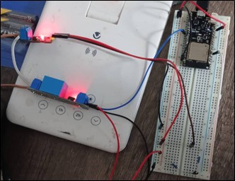
Close-up of the sensing and control circuitry. The voltage divider (10kΩ / 20kΩ) between the ACS712 output and the ESP32 ADC pin is visible here, scaling the 5V sensor signal down to 3.33V.


▶ My Role
I was responsible for the two most technically demanding parts of this project: writing the ESP32 firmware from scratch and building the full React Native mobile app. Both pieces had to work together seamlessly — the firmware producing clean, structured data; the app consuming and presenting it in real time. Every line of firmware and every screen in the app was written by me.
The hardware side — PCB layout, component selection, power supply design — was a team effort. But the intelligence of the system, the logic that makes a collection of components into a smart plug, lives in the firmware and the app. That was my work.
▶ Firmware I Wrote
Main loop. The firmware runs a continuous loop that coordinates six independent tasks without blocking. Every second it checks Firebase for relay state changes and compares them against local state — if they differ, it toggles the relay to match the cloud. Every second it also checks whether the current time matches any active schedule and executes the programmed action. Every 2 seconds it collects 300 ADC samples from the ACS712, calculates RMS current, DC offset, and peak-to-peak, then writes the result to Firebase. Every 5 minutes it re-syncs the full schedule list. Every 60 seconds it flushes the accumulated energy bucket (kWh, average power, peak power, sample count) to Firebase under a timestamped key. Every minute it polls for an OTA firmware URL and triggers an HTTP update if one is present.
Energy calculation. At startup the firmware calibrates the ADC zero-point (assuming 0A during boot). From there, RMS current is derived as the root mean square of voltage deviations from that zero point. Power is calculated as: P (kW) = I (A) × 230V × 0.9 (PF) ÷ 1000. Energy is accumulated as: E (kWh) = P (kW) × Δt (hours), held in memory structs (EnergyBucket) keyed by minute, hour, and day before being written to Firebase.
BLE provisioning. I designed and implemented the full BLE provisioning protocol. The ESP32 exposes six GATT characteristics under a custom service UUID: control (relay on/off), state (current relay state with notify), provision (write Wi-Fi credentials), prov-status (provisioning progress with notify), reset (factory reset), and OTA (trigger update). On receiving credentials via the provision characteristic, the firmware auto-detects Base64 encoding, parses the SSID and password, disconnects from any current network, and attempts the new connection. It then writes back to prov-status: OK;192.168.x.x;PLUG001 on success or ERR;wifi_connect_failed on failure. The app reads the notify and confirms setup to the user without any polling.
Device onboarding & account linking. After the plug connects to Wi-Fi and Firebase, the firmware broadcasts its unique plugID back to the app via the prov-status characteristic. The app then writes a Firestore record linking that plugID to the authenticated user's UID — ensuring only the owner can read or control that device. Security rules in Firebase enforce this at the database level, making cross-user access impossible regardless of how the API is called.
Hardware-level challenges. The ACS712 outputs 0–5V but the ESP32 ADC only accepts 3.3V. I designed the voltage divider (R1 = 10kΩ, R2 = 20kΩ) that scales the signal to 3.33V while preserving proportionality — validated in Proteus before being built. An RC filter (1000µF + 100nF) on the 5V rail suppresses relay coil transients that would corrupt ADC readings mid-measurement. The 700mA AC-DC module gives 75% headroom over peak draw (~400mA) to absorb Wi-Fi surges and relay inrush without brownouts.
▶ Mobile App I Built
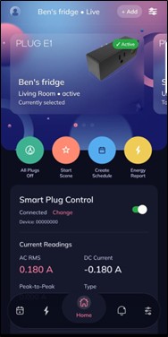
The React Native app is the user's entire interface to the system. I built every screen: authentication (Firebase Auth), device pairing via BLE, the main dashboard, energy graphs, insights, and the scheduling interface. The app subscribes to Firebase RTDB listeners so the dashboard updates in real time as the plug writes new sensor readings — no polling, no manual refresh.
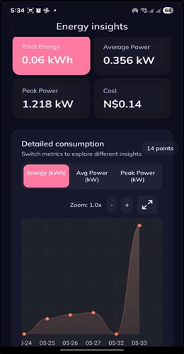
Energy graph screen. Plots historical kWh consumption over selectable time windows (minute, hourly, daily) by reading the nested energyHistory keys from Firebase. Each data point carries kWh, average power, peak power, and sample count — giving the user granular visibility into consumption patterns across any timeframe.
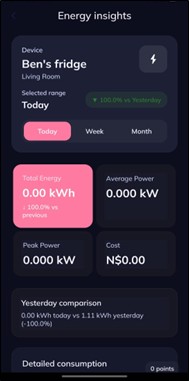
Insights screen. Surfaces usage trends and estimated cost based on accumulated energy data. Designed to give the user actionable information — not just raw numbers — to help reduce household electricity spend.
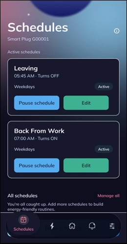
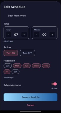
Schedule screens. Allows the user to create timed on/off rules specifying hour, minute, days of the week, and action. Schedules are written to Firebase under /devices/{id}/schedules and synced to the ESP32 every 5 minutes. Critically, the firmware executes schedules locally — so automation continues running even if the phone is offline or the app is closed.
Firebase schema I designed. The RTDB schema separates device info, relay state with change history, latest sensor data, energy history (minute/hourly/daily buckets), schedules, and OTA status into clean, independently updatable paths. This structure lets the firmware and app read and write only the nodes they need — keeping bandwidth low and latency minimal.